This page is about another homemade semi active TRE using a transistor to do the switching.
Home of the "Smart" TRE that automatically switches off in neutral. Designed in June 2003 and copied by most. It'll only work if you have a working neutral light though.
TRE Modification
Features and operation
This TRE is semi active like the relay one I built. This means it will not affect the neutral map, but all gears are remapped to either 5th or 6th selected by the resistor value chosen when it is assembled. I didn't include a switch in this one, but it is an easy addition if it's really wanted. I've never had the need to switch my SATRE off, so I haven't bothered with one on this version. Plus the main reason for working on this transistorised version is that it is a simple 3 wire design that doesn't need any extra cables except the ones that run from the GPS - ECU plugs.
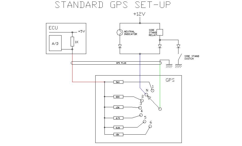
The operation is fairly simple. When the bike is in neutral and the neutral indicator is on, the base of the transistor is tied to ground so the transistor is off. When it is off it is seen as an open circuit by the ECU. The GPS signal to the ECU is open when in neutral when the wiring is stock. So all is good.
When the bike is in any gear (not in neutral) there is an effective +12V on the neutral indicator wire (as long as the globe is not blown). This +12V using miniscule current can saturate / turn on the transistor. When the transistor is on, it ties the ECU GPS cable to ground via a 15K ohm resistor which is exactly what happens in 6th gear when the wiring is stock.
Benefits
- 3 wire design.
- No moving parts.
- Doesn't affect the neutral map.
- Idle speed is not affected.
- Doesn't affect starting the bike.
- No need to remember if it is off or on.
Disadvantages
- The neutral indicator must be fitted and working.
Building and installing of my TRE
Luckily for me all of these things I needed I had lying around the garage. To go and buy these from the local Radioshack shouldn't set you back more than a few dollars. You'll only need some basic tools. Some solder and a soldering iron might be the only items some might not have.
Components
- 1 X BC549 NPN transistor or equivalent (2222a, there are plenty that can be used)
- 1 X 15K ohm resistor (for 6th gear) Or 6.8K ohm resistor (for 5th gear)
- 1 X 47K ohm resistor
- 1 X Project box or tube to put the lot in
- 1 Project bread board cut down to suit the enclosure
- Off cuts of wire and cable etc. I used and old joystick lead to run from the GPS plug to the TRE
Tools
- Pliers
- Knife
- Cable Strippers
- Screwdrivers
- Soldering iron and solder
Testing
Testing that the unit is working is pretty straight forward. Use a high impedance digital multimeter set on volts DC. On the Pink / Red wire that goes to the ECU you should get the following readings to ground / frame / black-white trace wire or even the battery -ve terminal
- In neutral, close to 5.08VDC
- In all gears using a 15K resistor, close to 4.70VDC
- In all gears using a 6.8K resistor, close to 4.38VDC
(The Pink / Red wire that goes to the ECU is the one out of the TRE (i.e. To the side of the 15K resistor that goes to the ECU). The ground is any wire that is black with a white tracer, or even the -ve terminal on the battery.)
Or when testing between the Pink / Red wire that goes to the ECU and to +5V
- In neutral, 0.00VDC
- In all gears using a 15K resistor, close to 0.313VDC
- In all gears using a 6.8K resistor, close to 0.643VDC
(The Pink / Red wire that goes to the ECU is the one out of the TRE (i.e. To the side of the 15K resistor that goes to the ECU). The +5V is the red wire that goes to the throttle position sensor (TPS), atmospheric pressure sensor (APS), the intake air pressure sensor (IAPS) and the red in the ECU programming plug that you plug a Yosh box or TEKA SFI into).
ECU part numbers
I've included the ECU part numbers so you can work out if your '97 TLS has the original ECU in it or not. The 1997 TLS was up on power compared to the later models, but there were various other reasons for this, like the heads are different, lighter flywheel, smaller clutch etc (the lighter flywheel and lighter clutch will show up as more power on an inertial dyno). The 1997 model still has a GPS though, and alters the mapping depending on what gear the engine is in and would benefit from a TRE. I don't think there would be many 1997 models out there with the original ECU as they were all recalled to have the later generation ECU's. Check your ECU number and compare it to the list. I have no idea where the idea came from that the '97 TLS would not benefit / not behave the same as the others when fitted with a TRE. Perhaps simply because there isn't many commercial versions made for the '97 TLS. That is because the '97 TLS only had a two pin plug, not true plug and play unit could be made as a ground wire has to be connected and it's a limited market that uses the 2 pin plug compared to all the models that use the 3 pin plugs.
Here are the ECU part numbers: This information was lifted from here: TL1000S FAQ on Micapeak
32920-02F40 112100-0120 USA (original)
32920-02F41 112100-0123 USA (new, per Suzuki)


32920-02F00 112100-0070 UK & Australia (original)
32920-02F00 112100-0072 UK (original)
32920-02F00 112100-0090 UK (original)
32920-02F01 NZ & Australia (new)
The parts department at Suzuki GB says: "It seems that the 32920-02 part is a worldwide ID number for the ECU. The bit that starts Fxx signifies a variation in the ECU dependent upon the market for which it is intended (UK-F00, USA-F40). The bit which starts 112100-xxxx is probably a manufacturers number or a batch number."
I have a more comprehensive list of ECU numbers here >> here!
Circuit Diagrams
Here are some circuit diagrams.
The standard GPS & Transistorised set-up drawings.
|

|
Simple plug drawings
Here's how you would connect it to the wiring loom. The drawing on the left is simply splicing it into the existing loom. The one on the right is how you would connect it if you got hold of a set of OEM plugs. You can substitute the resistance value for a value of any gear you like (Busa's and GSXR1000 owners would want 6.8K for 5th gear to defeat their speed limiters) but for my TLS, 6th gear is just fine.


Here's a nice PDF of the transistorised TRE created by Glenn Cauley, a member on TLZone.net

Right click "save as".
Transistor orientation
I've had a few questions asked of me about transistor leg orientation. Here's a good site for information Transistor basics Just in case the page disappears I borrowed the following animations from it.


Commercial Manufacturers
Now I've put this information out in the public domain I wonder how long until we'll see this design in production and being sold around the globe as overpriced automatic de-restrictors /TRE's. How long until these start appearing on EBay sold as who knows under what marketing names and claims. This design appeared online November 2003 and I haven't seen any available yet.
If you use or copy this design for a TRE that is a 3 wire design that doesn't affect the neutral running of the bike and automatically switches when in gear all I ask is that you shoot me an email and hook me up with a handfull of OEM connectors and pins and sell them to me for what they cost you. Just so I can make a few up for my FI Suzuki riding friends.
Fat lot of good that paragraph did me. Smart TRE's are everywhere now.
Special thanks to etbadger who was a member on the old TLPlanet for planting the seed and sharing his version of it with me.