I captured some screen shots of the frontend I wrote using Visual Basic.
Dyno Frontend
This page may take a while to load as it has approx 300Kb of images in it
Source Code
I've added this page as I've recieved a few emails about my front end and data acquisition code. I've added the current source code for the Basic Stamp that I'm currently using as well. Eventually I will move over to a faster DA system, possibly using a PIC micro. But for the time being to speed
up developement I'm sticking with the stamp. The only thing I'm keeping close to myself is the entire source code for the frontend that I taught myself to write in Visual Basic. Plus it's still a little bit clunky and I'm not 100% happy with it. I know exactly what I want the final version to do, I just lost motivation and haven't finished writing the final program.
Contents
The main screen

(Click for a larger image 1200 X 648 - 99kb)
That's a screen shot of the main screen. I've tried to make the program as comprehensive as possible but still keep it simple. I had to draw up some of my own graphics for the buttons to try and show what each one does at a glance.
Across the top is, Open File, Make Run, Display in HP, Display in PS, Display in KW. Then if RPM is available this button is enabled, Display bottom as RPM, next, bottom in km/h, mph. If RPM data is available the torque buttons are enabled, first is no torque, then ft/lbs, then kg/m.
There is a drop down box to smooth the graph from 1 to 5 and finally a choice of background colours.
Down the side the buttons are, Close a run, Save a run, Print a run, Overlay a second run, Maximum run values, Scroll the run sampled values, Graph legend on or off, No gridlines, Vertical grid, Hoizontal grid, V&H gridlines.
Back to the top
Communications
|
This is the screen for setting up the communications. I've disabled all of the options except for the communication port number. I started on the frontend well before I started on the DA, so I included drop down boxes for all the variables that VB could handle, since I settled on the Basic
Stamp and had coded the baud rate etc into it, there was no need to have them variable. It is a simple fix to enable them again or change them for different communication options.
|

|
Back to the top
Entering the Drum specifications
|
All of these values are password protected. Before any changes are accepted the correct password must be entered. This stops others from altering the specifications, or accidental altering of the specifications which will have a great impact on the graphed data.
As you can see in this shot, there is a choice for entering a known moment of inertia or entering very basic drum specs and having the MOI calculated for you. I calculate my own MOI and entered the value. Using the the other options calculated it pretty close, but I wanted to add the values for my stub axles as well, even thought they were of a very little number.
The bottom part of the window is to do with the data acquisition side of the drum.
Pulses per revolution is pretty straight forward, it is simply how many pulses the DA unit receieves for every revolution of the drum.
The clock frequency in MHz is a bit more complicated. It is so the front end can calculate the acceleration of the drum. The basic stamp increments its timer in 2us incremements, that is each number received is 2us, so a value of one = 2us, 10 = 20us etc. The Program I wrote for the basic stamp times the length of time between and the number is 2us increments this = .5Mhz or 500,000 / second. If I used a stamp or a timer that timed in 1us increments, then this value would be 1MHz (1,000,000 counts per second).
|

|
Back to the top
DA and Drum calibration window.
|
This window is for calibrating the DA unit and / or Drum losses. The most important value in this lot is the "pulse frequency (hz)". If you have a frequency generator that can output a known frequency and feed it into the DA unit, at 0% correction this values should be identical. If it isn't you have to adjust the slider until it is equal. Using this percentage, you then have to add it to the percentage loss of the drum bearing and windage etc. The 7% shown in my example is too high. What I did was build a multivibrator out of a LM555 timer. I fed this into a CRO at work and got its output frequency (19KHz). When connected to the stamp I get 19KHz. So the only correction I have to allow for is the Drum losses. Other than calibration, the window is handy for looking at the data from the drum in real time. Two of the drum specifications are displayed at the top of the window, pulses per revolution and its diameter. Before any changes can be made, you'll be promped for a password and if an incorrect password is entered the changes are ignored. As in the Drum Set-up this stops others from altering the specs, or accidental altering of the specs which will have a great impact on the graphed data.
I have a program made for calcultating the acutal drum losses, but I haven't got around to using it. All it involves is spinning the drum up to 180mph or so, jacking the bike off it and do a negative run down run, invert the results it and add those values to any run done. This would compensate for the actual drum losses.
|

|
Back to the top
Making a run
|
Making a run.
This is the window that pops up when you're about to make a run. It displays the minimum start speed calculated by the program according to the drum specs. Atmospheric conditions are entered for correction values if desired. Once the "Start Now" button is clicked the DA unit monitors the pulse duration from the proximity switch and then starts transmitting data as soon as the desired start speed is reached
|

|
Back to the top
Calculating a Drum to Engine ratio
|
Ratio
|

|
Back to the top
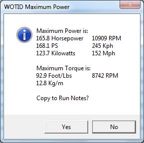
Displaying maximum values recorded
|
Max values
|
|
Back to the top
Scrolling the values recorded
|
Scrolling values
|

|
Back to the top
Basic Stamp Source Code
If you read about the PBasic programming syntax, I think you'll find this program real simple.
DIRS= %1111111110100000

'Date 04-01-03
'WOTID DYNO HARDWARE
'Added run down loop for working out losses of drum
'Test loop changed to end automatically, must be restarted by frontend

'Input data is C,P THEN SSSSS <cr>
'Where C is A for About, S for Start, G for Gear, T for Test, R for run down
'Where P is 0 for no spark pulses, 1 for spark every revolution, 2 for every 2nd revolution
'Where SSSSS is for 0 to 65535 for start figures
'S1,23400<cr> = Start,Spark every rev,23400 start count.

'VARIABLES
Sample1	var Word	'1st Sample
Sample2	var Word	'2nd Sample
Sample3	var Word	'3rd Sample (For RPM Calculations)
Sample4	var Word	'4th Sample (Used for Test Loop)
StartValue	var Word	'Value reached before transmission of Data
strIn1  	var Byte(3)	'String in with Starting details
REPS		var Nib	'Repetitions for Dwell and Gear Ratio Calculations

'CONSTANTS
DrumIn  	con 0	'Pin Drum Data in on
RPMIn		con 1	'Pin RPM Data in on
Tx		con 5	'Pin 5 Serial output (Transmission)
Rx		con 6	'Pin 6 Serial input  (Receiving)
Flow		con 4	'Pin 4 Flow control  (Transmission permanently held low)
RPM_HiLo	con 1	'RPM input (1 = 0-1-0) or (0 = 1-0-1) transitions
Drum_HiLo	con 1	'Drum input (1 = 0-1-0) or (0 = 1-0-1) transitions
COMM		con 32	'Communication @ 19200,8N1

strIn1(2) = 0		'Put Array Length in last array
StartValue= 000		'Initialise RunStart to 000
High 7			'OK Led

Start:
serin Rx,comm,[str strIn1\2\cr,DEC StartValue] 'Serial in end after 2 bytes or carriage return
then a decimal value.
if strIn1(0) = "A" then About
if strIn1(0) = "S" then Calc_Start
if strIn1(0) = "G" then Gear_Ratio
if strIn1(0) = "T" then Test
if strIn1(0) = "R" then Run_Down
if strIn1(0) <> "A" or "S" or "G" or "T" or "R" then Reinitialise
goto Start

Reinitialise:
StartValue = 000
strIn1(0) = " "
goto Start

About:
serout Tx,comm,[cr,"WOTID Beta Version By Steve",cr,"File name DYNO0103.BS2",cr]
goto Start

Calc_Start:
if strIn1(1) =  "0" and StartValue = 0 then Drum_Only
if strIn1(1) <> "0" and StartValue = 0 then Drum_RPM
if StartValue > 0 then Auto_Start
goto Start

Auto_Start:
pulsin DrumIn,Drum_HiLo,Sample1
if Sample1 = 0 then Auto_Start
if Sample1 < StartValue and strIn1(1) = "0" then Drum_Only
if Sample1 < StartValue and strIn1(1) <>"0" then Drum_RPM
goto Auto_Start

Test:
For Reps = 1 to 15
pulsin DrumIn,1,Sample1			'Drum Pulse on Pin DrumIn 1-0-1 pulse
serout Tx\Flow,comm,[dec Sample1,cr]
next
goto Ending_Run

Gear_Ratio:
For Reps = 1 to 10
pulsin DrumIn,Drum_HiLo,Sample1		'Drum Pulse on Pin DrumIn
pulsin DrumIn,Drum_HiLo,Sample2		'Drum Pulse on Pin DrumIn
serout Tx\Flow,comm,[dec Sample1,",",dec Sample2,cr]
next
goto Ending_Run


Ending_Run:
serout Tx,comm,["T",cr]
goto Start

Drum_RPM:
pulsin DrumIn,Drum_HiLo,Sample1		'Drum Pulse on Pin DrumIn
pulsin DrumIn,Drum_HiLo,Sample2		'Drum Pulse on Pin DrumIn
pulsin RPMIn,RPM_HiLo,Sample3			'Rpm Pulse on Pin RPMIn
serout Tx\Flow,comm,[hex4 Sample1,",",hex4 Sample2,",",hex4 Sample3,cr]
If Sample1 < Sample2 then Ending_Run
goto Drum_RPM

Drum_Only:
pulsin DrumIn,Drum_HiLo,Sample1			'Drum Pulse on Pin DrumIn	 240 microseconds + pulse length
pulsin DrumIn,Drum_HiLo,Sample2			'Drum Pulse on Pin DrumIn	 240 microseconds + pulse length
serout Tx\Flow,comm,[hex4 Sample1,",",hex4 Sample2,",0",cr]		'1200 us + 6250 (data Tx) = 7450us
If Sample1 < Sample2 then Ending_Run					'470 microseconds
goto Drum_Only									'245 microseconds


Run_Down:
pulsin DrumIn,Drum_HiLo,Sample1						'Drum Pulse on Pin DrumIn	 240 microseconds + pulse length
pulsin DrumIn,Drum_HiLo,Sample2						'Drum Pulse on Pin DrumIn	 240 microseconds + pulse length
serout Tx\Flow,comm,[hex4 Sample1,",",hex4 Sample2,",0",cr]		'1200 us + 6250 (data Tx) = 7450us
If Sample1 > Sample2 then Ending_Run					'470 microseconds
goto Run_Down									'245 microseconds


'By setting flow control 440 microseconds is saved over serout with no flow control.
'(Flow control added pin 13).
'By Transmitting hex4 takes 1200 microseconds to interpret and start transmission.
'Other saving using Hex is a 'max of 4 bytes sent FFFF compared to 5 decimal bytes 65535. Total time = 2395 + pulse time
'+ data transmission of 19200 bps. This compares to 5195 microseconds using no flow and
'dec conversion and data transmission has extra byte(s). Another 715 microseconds per sample
'could be saved by filling the program with heaps of pulsin and serout
'before doing the comparison and goto. Also extra variable space is available for more
'samples before serout.
'Weigh up the advantages and disadvantages of sending upto 8 variables at a time.
'My calculations come up with 521 microseconds per byte including start and stop bits.
'(leading zero should = 521).
'This is using the timing information from EME Systems of 180 microseconds serout hex4,
'(Variable Word).
'For drum only: 4 bytes + comma + 4 bytes + "comma and 0"(2 bytes) + cr(1 byte) = 12 bytes = 6250
'microseconds.
'Therefore 1 loop of Drum_only takes 6250 + 2395 + pulse times = 8645 microseconds = 8.645ms +
'both pulse times.
'If pulsin pulses give a count value of less than 4322 (H10E2) (8.6ms) then a revolution will
'be missed because pulse1 + pulse2 + 8.6ms to loop is longer than the pulse time! Also check
'dwell angle must be exacly 180deg 50%.
'Dwell angle taken care of by D type flip-flop. Make sure tags are evenly spaced,
'i.e 180, 90 45 degrees apart.
'End Character changed to T for terminate can't use E because this is also a hex value that
'confuses the frontend.
Back to the top